
Feel free to ask if something in the movies below doesn't seem to make sense. But if you have some semicondctor device physics background all you need is to watch it a few times. You'll gain a lot more by figuring it out yourself. Don't be tempted to click Email Nir. Some answers are in the paper by Yana and Nir "insights..." linked above
| Movie one: reaching equilibriun |
|---|
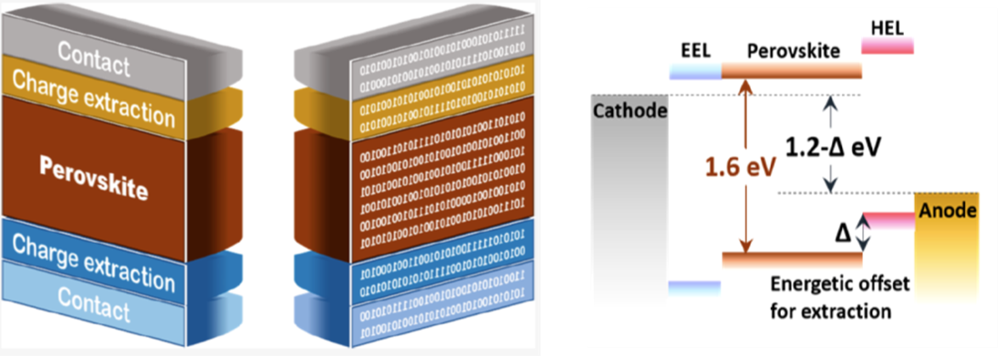
Let's assume that your three layers (Electron Transport Layer/ Perovskite/ Hole Transport Layer) are fabricated and you are about to let the electrodes make contact with the ETL/HTL with V=0. In these simulations all layers are intrinsic (undoped).
Charges will flow in and ions will redistribute until equilibrium is reached. In the simulation, we can see the instantaneous response of the electrons and holes in the perovskite layer.
Because the ions are so slow, at some point, to reduce the simulation time, we'll boost their mobility to reach steady state (current=0 and voltage=0). The mobility-boost creates an artificial transient current that decays as the ions settle into their final distribution. The dielectric constant for organic TL and perovskite are 3 and 30.
The dashed line in the energy band diagram is a guide to the eye (not Fermi level)
Note the 0.3eV mismatch of the HTL and that between the ETL and the cathode we inserted a thin layer to mimic BCP with deep HOMO.
| Movie two: Turning 1 Sun on with V=0 |
|---|
After reaching equilibrium (V=0 & dark) we turn the sun on.
Charges build up in the perovskie layer and photocurrent ramps to Jsc=-22mAcm^-2.
Because the ions are so slow, at some point, we'll boost their mobility to reach steady state within your screen width.
The artifact of boosting the ion-mobility is the creation an artificial transient current that decays as the ions settle into their final distribution and the current is again electronic (and not ionic).
The dielectric constant for organic TL and perovskite are 3 and 30.
Note the 0.3eV mismatch of the HTL.
| Movie 3: With the cell at V=0 & 1Sun we stepped the voltage to 1.2V (~MPP). Ions are practically imobilie during the electronic RC. |
|---|
After reaching steady state (V=0 & 1Sun) we stepped the voltage to V=1.2V which is a bit beyond the maximum power point of this cell.
The movie starts just after stepping the voltage to 1.2V
The charging current is positive and as it decays the total current switch back to being negative, J(V=1.2)=-12mAcm^-2.
The charges build up at the HTL interface and we see an interface-dipole, made of e-h, being formed.
This dipole reduces the 0.3eV mismach between HTL and perovskite.
The dashed cyan line denotes the Anode's energy.
Note that, during the electronic transient, the cations have not had a chance to change from their V=0 distribution. We'll speed them up in the next movie.
The dielectric constant for organic TL and perovskite are 3 and 30.
| Movie 4: After the electronic transient ended (V=1.2 & 1 Sun) we speed up the ions to check their effect . |
|---|
Following the electronic transient we speed up the cations which creats artificially high ionic current.
The most striking effect is that, as the ions stabilize,the charge density distributions vastly change. However, the steady state current is still the same.
The dashed cyan line denotes the Anode's energy.
The dielectric constant for organic TL and perovskite are 3 and 30.