Sub-Nyquist Ultrasound Imaging Tanya Chernyakova, Yonina C. Eldar and Alon Eilam
Introduction and Main Results
Introduction:
Ultrasound imaging uses high-frequency sound waves to create images of soft body tissues, such as muscles and internal organs. The images are captured in real-time, and with proper frame rate can show movement of the body's internal organs as well as blood flowing through blood vessels.
An ultrasound image is composed of a set of lines with intensity that represents the tissue elements along each line. A line in the image is achieved by transmitting a pulse to the tissue in a certain angle. During the pulse propagation, echoes are scattered by acoustic impedance perturbations in the tissue. The echo signals are received by a phased array of transducers, sampled and digitally integrated in a way referred to as beamforming. The beamformed signal is translated to an image line corresponding to the transmission angle. Beamforming provides optimal focusing per depth in the tissue, enhances signal-to-noise ratio (SNR), and improves angular localization.
Contemporary medical ultrasound systems implement beamforming digitally on time domain signal samples. In order to achieve high beamforming resolution, the required sampling rates are significantly higher than the Nyquist rate of the signals, resulting in considerable amount of data that needs to be stored and processed. In our work we show that beamforming can be performed equivalently in the frequency domain. This allows exploiting the low bandwidth of the ultrasound signal and bypassing the oversampling dictated by digital implementation of beamforming in time for any signal, without the need to assume any particular structure.
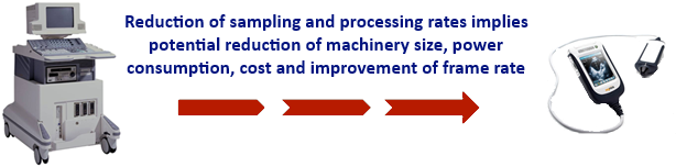
Further reduction in sampling rate is obtained when the signal's structure is taken into account. In this case only a portion of the signal’s bandwidth is required to reconstruct a high quality image using Xampling methodology. The saving in sampling rate per each transducer element is multiplied by the amount of transducers, which can be from a few dozens to several thousands. As a result, considerable sampling and processing rate reduction is achieved. This provides for smaller system size, power consumption and cost and can be used as an enabling technology for high resolution volumetric imaging, wireless ultrasound, and cloud based distributed processing of ultrasound images.
Main Results:
We have developed and implemented the concept of beamforming in the frequency domain, which is applicable to any signal. The result is completely equivalent to standard time-domain processing, but allows to bypass the oversampling dictated by digital implementation of beamforming in time [1].
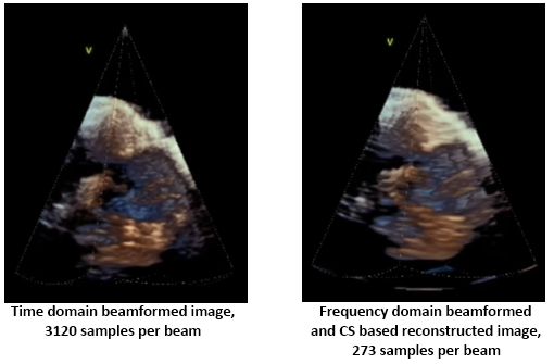
Further reduction in sampling rate is obtained when only a portion of the beam’s bandwidth is used [1]. In this case the detected signals are sampled at a sub-Nyquist rate, leading to up to 28 fold sampling rate reduction per element. In order to reconstruct the beamformed signal from its partial frequency data, we rely on the fact that the beamformed signal obeys a finite rate of innovation (FRI) model and use Compressed Sensing (CS) techniques [2],[3].
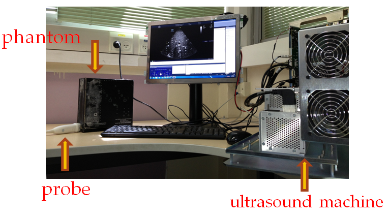
In our laboratory, frequency domain beamforming is implemented on a state of the art ultrasound machine [4]. Low-rate processing is performed on a 64-element cardiac probe. We demonstrate our methods on in vivo cardiac data and show that reduction up to 1/28 over standard beamforming rates is achievable.
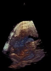
Fig. 1: Image resulting from time domain vs. frequency domain, CS based beamforming.
Enable high quality, portable and low cost system design, by reducing the required sampling and processing rates.
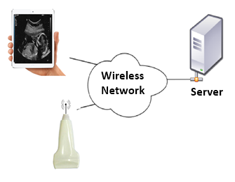
Ultrasound image processing in a computer network cloud is possible based on the low channel data rate between the sampling and processing units. The image can be displayed on a hand-held portable unit.
Sub-Nyquist beamforming is an enabling technology for high resolution volumetric imaging. Transducer arrays for high resolution volumetric imaging contain thousands of elements, so that a considerable reduction of data rates can be achieved with our approach [5].
Beamforming Process
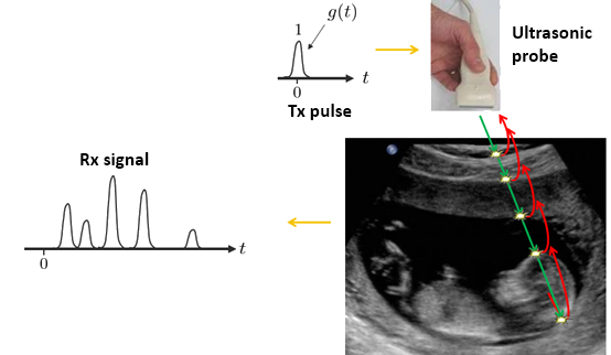
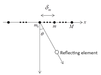
Ultrasound imaging is performed by transmitting a pulse along a narrow beam from an array of transducer elements. During pulse propagation, echoes are scattered by acoustic impedance perturbations in the tissue, and detected by the array elements. The data, collected by the transducers, is sampled and digitally integrated in a way referred to as beamforming. Beamforming is comprised of averaging the detected signals after their alignment with appropriate time-dependent delays. It allows reception in a predefined direction, corresponding to the transmission angle, and optimal focus at each depth.
An ultrasonic probe is composed of a set of transducer elements. The directional beam is generated by transmitting the same pulse with different phases from each element, resulting in constructive interference in a certain angle and destructive interference in other angles. The same phased array of transducer elements is used in the receive path for directional reception of the echo signals. In time domain beamforming, the signals received by the transducer elements go through non-linear delays defined by the beam angle and the probe geometry. The delayed signals are averaged to generate the beamformed signal, as shown in Figure 1.
Figure 3: Beamforming in the time domain.
For an ultrasonic probe with M transducer elements, the beamformed signal in direction θ is created by a weighted average of the non-linearly delayed signals φm(t;θ) received at the transducer elements:
In order to implement the non-linear delays in (1) digitally, the received signals must be sampled on a sufficiently dense grid. Therefore, in the time domain the required sampling rates are significantly higher than the Nyquist rate of the signal and can be as high as hundreds of MHz.
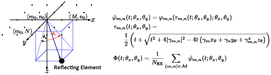
Data and processing burden are quadrupled for volumetric imaging, since the geometry has an additional dimension. Yet the beamforming principle remains the same, as shown in Figure 2:
Figure 4: Beamforming in volumetric imaging.
Beamforming In The Frequency Domain
Even though beamforming is a non-linear process, we show that it can be translated into the frequency domain, paving the way to substantial reduction in required sampling and processing rates [1], [3].
Beamforming in the frequency domain is based on computing the set {c[k]} of Fourier series coefficients of the beamformed signal Φ(t;θ) as a weighted average of Fourier series coefficients cm[n] of the signals {φm(t;θ)} which are detected by the transducer elements:
The weights {Qk,m;θ[n]} are Fourier series coefficients of a distortion function qk,m;θ(t), which effectivly transfers the non-linear time dependent delays into the frequecy domain. The distortion function is signal independent and is computed off-line. Its Fourier coefficients, {Qk,m;θ[n]}, are characterized by a rapid decay. Therefore in order to obtain a set {c[k]} of size M of the beam's Fourier coefficients, we only need M + N1 + N2 Fourier coefficients of each one of the detected signals, where N1,N2<<M. The required set Fourier coefficients can be obtained from their generalized low-rate samples using the Xampling Sub-Nyquist approach [5], [6-9]. The important point is that using Xamping, one can obtain M Fourier coefficients using only M samples, which are obtained by appropriate pre-filtering followed by low rate sampling.
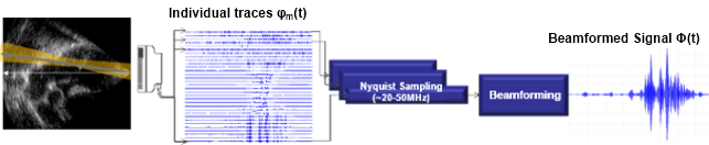
The overall system structure is depicted in Fig. 3. Detected signals are filtered and sampled at a low rate, their Fourier coefficients are then obtained and beamforming is performed directly in frequency at a low-rate.
Figure 5: Frequency domain beamforming.
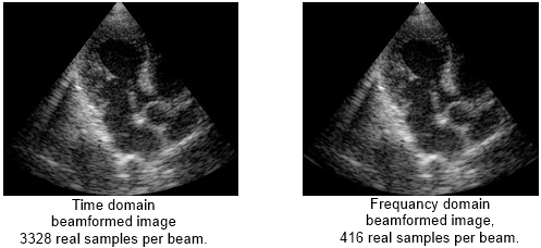
Images obtained by time domain vs. frequency domain beamforming are shown in Fig. 4. The images are virtually identical, while 8 fold savings in sampling and processing rates was achieved using frequency domain beamforming.
Fig. 6. Image resulting from time domain vs. frequency domain beamforming.
Further rate reduction is achieved when the detected signals are sampled at a sub-Nyquist rate. In this case beamforming in frequency yields a subset of beamformed signal frequency components. To recover the beam from its partial frequency data we exploit the signal's structure that was not considered so far, by using ideas of Xampling and FRI. The important point is that both sampling and beamforming are performed at a low rate.
[5] M. Birk, A. Burshtein, T. Chernyakova, A. Eilam, J. W. Choe, A. Nikoozadeh, B. T. Khuri-Yakub and Y. C. Eldar, "Compressed 3D Ultrasound Imaging With 2D Arrays", IEEE International Conference on Acoustics, Speech and Signal Processing (ICASSP 2014), pp. 6919-6923, May 2014.